Combing Machine Relief and Raster Toolpaths
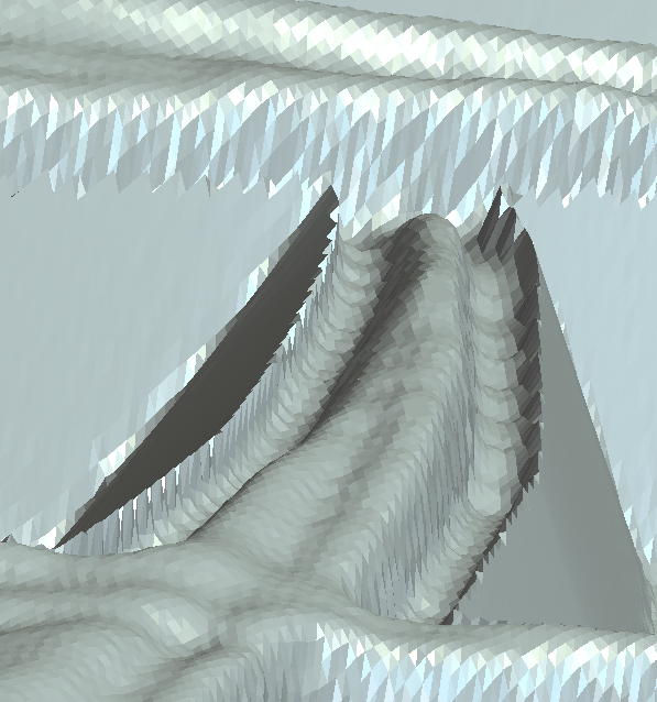
I am making a layered sign and using both text and 3D reliefs. I created a vector boundary of the relief so that the machine relief toolpath stays around the 3D relief. From there I am using a raster toolpath to create a v-bit carved edge profile around the relief and subsequent text. My issue is the mesh point between the raster toolpath and machine relief. I have attached an image of what I call the mountain edge effect that the simulation shows. How can I create a smoother profile where the 3D relief ends and the v-bit edge profile begins? My vector boundary is located in the middle of the bit valley shown in the simulation around the 3D relief.
Comments
In choosing your toolpath you are given a few things to choose (profile) start depth, finish depth, then tolerance, this last one is kind of important to stop the jagged edges, In the raster toolpath you will have angle, tolerance and allowance, again tolerance is important. In modeling what did you choose for your resolution, this the higher it is the better your outcome will be.
Follow these and your out come will be a lot better.
mike
My tolerance is set to .0001 but for some reason the v-bit cutter doesn't come over enough. Thinking more about it my cut sequence. I have 2 layers with the top layer have just v-bit work around lettering down to a depth of 0.1 inches. The second layer is where I have a 3D relief and v-bit work. My issue is that the setting probably has the outside of the bit shank (0.25 inch shank) go up against the line so I need to move my line over so that my v-bit comes far enough over to match the depth of the cut (0.1 inches).
No matter how I move over my V-bit I still get the trench effect. Even if I do the second layer v-bit first and then 3D relief the simulation still gives me the trench.
Matthew,
Why do you need the v-bit? A straight end mill will give a nice finish. Why are you wanting to run a v-bit in a raster toolpath? If you use the profile toolpath using the v-bit you can use along the vector, inside or outside vector, when you use the raster toolpath it's everything inside of the vector that will be cut.
Are you using maker, maker plus, or the complete version of Carveco.
Is this a rose, a tulip or what? What is the height of your model? Is there any undulations outside of your flowers and text? Or is your surface basically flat, if it's flat then run a profile toolpath along the vectors at a set depth (how ever deep your model is so you don't cut through your material).
Here are 2 pics one with a .100 ball end and a profile with q 1/16 end mill, to give you a hint of what is better and really faster.
mike
I am creating a stacked text sign. For each layer I use a vcarve toolpath with a roughing end mill to create an angled border around everything. I don't need to have an angled border around everything but I appreciate the tip to use a profile toolpath around the border of the relief. What I will probably need to do for the second layer with the relief is carve the borders of the relief, text, and border with a profile toolpath then use an area clearance toolpath to remove the fill.
The flower is a tulip and I am using Maker Plus.
One last part that I think is giving me problems is placing my relief at the correct depth in my model. I have 0.75" material and my first layer will remove 0.1" material. My relief I only want to go 0.15" depth to give me a total of 0.25" in total carving depth but when I setup my machine relief toolpath the carve goes deeper than the 0.25" I am looking for.
Matthew,
I'm going to have to take time learning maker plus, I use the easiest of carveco the full version.
I did see that in maker plus there is add a draft. You can do a lot with it to give you angled boarders, you don't necessarily need to do the full file, just where you like by node editing, along with the copy paste routine.
In the meantime I'll have to try to understand what you're doing (sometimes there are words that are added that sort of block understanding, or getting a full picture, sometimes I get fixated on some word and get lost) (This has to do mainly with 2 different software packages and what you can do or can not do in either) Like I said I use the easiest, I have and use layers (both the relief and vector layers) to accomplish what I wish, everything is in one file.
From what I understand you have a couple files, one you do the angled stuff the other you bring in the model (I think this is what you mean by stacked)
mike
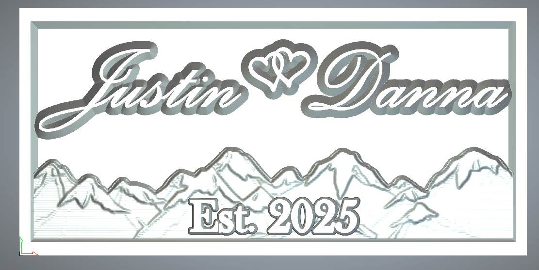
The "Stacked" term is that I have graphics at different levels that overlap into 1 design. Attached are pictures of another project I did that uses Mountains instead of tulips. Still have issues with meshing the angled border with relief but I was able to get it close enough to work.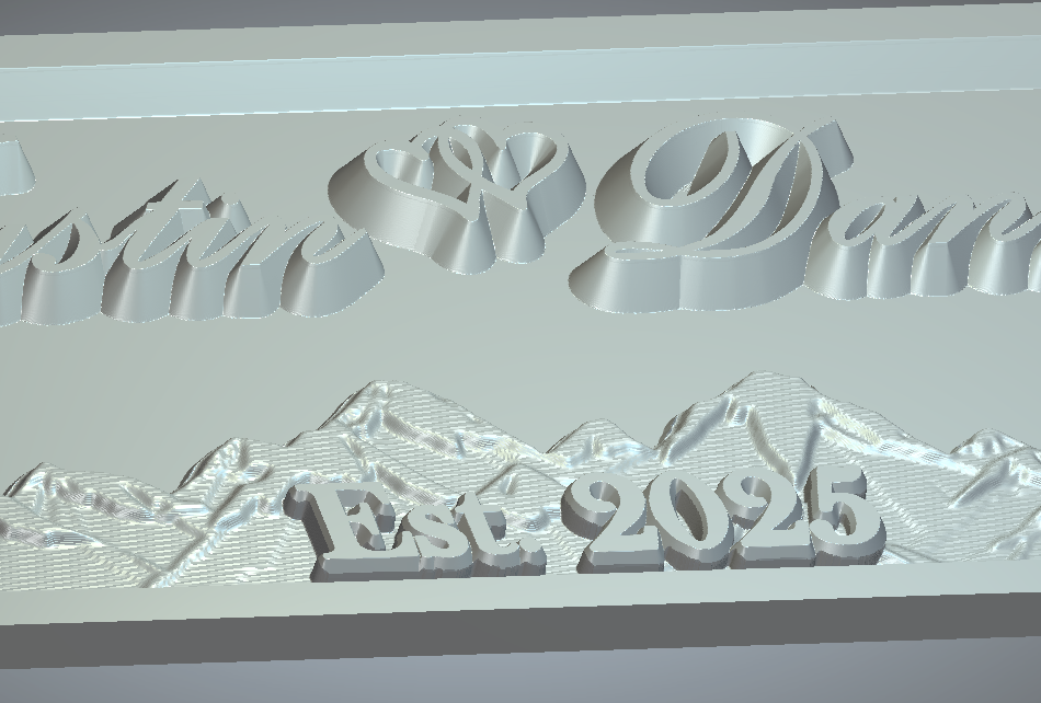
Okay, I'm working at how to do things in Maker Plus. What I did is make a new model saved it made a vector, made a half oval used node edit to change the look for the shape to extrude for an outside border shape, saved this, brought in a daisy made a swirly line used paste on a curve at 2 inches (came out with 7) centered using f9, saved reset the file (still had the vectors) used F12 for the shape editor brought it up about .150 then used the DRAFT tool to give a 25 degree, imported the file I saved used ADD on the cookie cutter saved said file, reset started a new vector layer had fun with the transform tool on a rectangle, next added an oval large enough to just about cover the rectangle, used shape editor to give it a height to get over the daisies used the smooth to smooth the ends to give a look of no bumps, used text tool then used shape editor on the text with about .100 added height a long with a square shape at I think 25 deg., used the shape editor on the rectangle to round over the edges a little brought in the original file merged high in the cookie cutter merge high cookie cutter,
Sorry about the rambling I just wanted to get most of the steps I took down.
I will work on trying to understand the other stuff you do, you should really take a look at the "Draft" tool, this way you'd only have to run a raster toolpath using a 1/4 inch a 1/8 or a 1/16 inch ball ends
mike
Matthew,
I looked closely on your first pic, it appears as though the vector you're using isn't at the lowest level, if you can bring your vector in closet to the tulip and the stem I think you'd be golden. You need sharp edges right now you have a dish then a rise before the edge, to look use the shape editor bring it up you'll see what I am talking about. If you need a different tulip, if I can find my password to send you a link I'll do that, though I probably threw it away, I try to find out how to send you a private message through the forum (I'm at a loss for that too). The file is only 350 k so it's not large.
mike
Matthew,
Ideas:
I was thinking If you used the shape editor to bring up your relief say .025 to .50 then use your v-bit, see how that would turn out, or use the "draft tool" to put a 25 to 40 degree bevel on it (reason for this it to just do one tool path, raster), you could also use the shape editor to add height and restrict the angle of the square shape to say .05 you could change the angle to anything you want, it's really cool because you'll be able to see what it will look like before committing to it.
If you were to use the "Offset vector" tool then delete everything outside of the vector, repeat until you got it right you could then try that 45 bit again to verify.
mike
Matthew,
I was thinking again (dangerous) anyway if you were to take the offset vector tool and enlarge the vector say .04" (if you use a 1/16" ball end) you could do everything you want the way you want but use the larger vector to run a raster toolpath that should take care of the raised part and it should look meshed real nice. Just a thought.
mike
Matthew here's a tulip I started a bout a year or so for a fellow, he declind but its here if you want I do believe you'll have 3 days to get it.
https://we.tl/t-QsYBW6Zho1
mike
Hey Mike,
Appreciate the feedback first off. Currently I have worked a combination of 2D raster using an end mill to remove most material and the v-bit at the perimeter. Then, 3D relief the tulips. Final step is a 2D raster to remove the v-bit edge around the tulips and then profile paths with bullnose to clear out the tight areas.
Probably inefficient with the multiple tool changes, but I only have 2 weeks till I need to get this done and I don't have enough time to learn the Draft tool properly. Definitely interested in being more efficient in making this design. Also interested in the carve time that a single raster path would create because a 1/16" bull nose would take forever to carve a clean look even if you could do it in one path.
I have stuck with 2 sometimes 4 toolpaths, I should check everything out and work with them but I figure if it works well why change, plus I have too many things running through my head to remember much, I, myself don't think there is anything wrong with the way you're doing it. You might check out trying 1/4 inch ball end first, an 1/8 ball then the 1/16, I have had a saw shop grind me down an 1/8 to .1 it does a nice finish so I don't us a 1/16 much ( do when I have some detail I wish to have clearer). I now use a 1/4 ball then .1 ball. You might try to increase the speed to see what happens, though those little things are quite spendy.
You might so get a flap sander from Klingspor, (they have a few different ones) they work great, I use the 120 grit a bit.
mike
Please sign in to leave a comment.