Every toolpath saved has a starting point offset in both X and Y
Been trying to use Carveco Maker for a week now and have a problem I just can't fix. To test I have a piece of pine that is X= 107.95mm, Y= 87.96mm, Z = 9.83, that I am trying to surface flat using my recently purchased Genmitsu 4040-Pro. I have homed it to the lower left corner at 0,0,0 as the first screen shots of both in Carveco Maker and in UGS to illustrate the issue clearly. In Carveco Maker everything looks correct including the home/starting location, but if you look at the UGS version the toolpath is offset by a very large amount and even the size of the piece is wrong. I have also included a screen shot of the machine format I am using which is SainSmart 4030 PROover with Probe (mm) (*.tap). I even tried to SainSmart 3018 Pro with Probe (mm) (*.tap), but same problem. I even went so far and use UGS GRBL (mm) (*gcode) and still everything is offset to the upper right corner without any rhythm or reason. I've copied a file from my computer to an SD card and put it in my Genmitsu 4040-Pro Offline Controller. I really like the interface and all the features of Carveco Maker and the price range is acceptable for a starting hobbyist, who might want to later on sell stuff at a local flea market, but I really don't know how to get past this hurtle. I've even checked and confirmed the "Set Position" is set to bottom left pixel. When I create a Model the job origin is also the lower left corner. If you look very carefully you'll see that this issue has something going on with Carveco Maker. What is it I don't know. Any help would be greatly appreciated. Thank you for any assistance you can give and have a blessed day/night/afternoon/morning.


Comments
Hi Darin Murphy,
Your supplied set of screenshots show that you've:
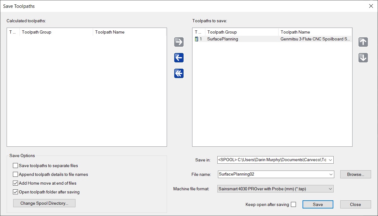
Nothing in the screenshot of your "Pine_10774x8796_Planning00.art" model file suggests there is an origin offset issue. When working in metric units within Carveco Maker and using Universal Gcode Sender as your machine controller, you should select only the "UGS GRBL (mm) (*.gcode)" post processor option from the Save Toolpaths dialog's Machine file format list.
Therefore, please save your calculated "Genmitsu 3-Flute CNC Spoilboard" toolpath again from your "Pine_10774x8796_Planning00.art" model file using the "UGS GRBL (mm) (*.gcode)" post processor option, load the resulting .gcode file into Universal Gcode Sender, and then include a screenshot of your results in Universal Gcode Sender when replying in this topic.
Thanks for your time and cooperation.
Please also note the following:
Thanks again for your time and consideration.
Thank you for your quick assistance to the issue I am having. I am including some additional screen shots to show what size I have the size is set at, as well as the code of the surface planning tooling, since it's very small. As you can see there is no G54 in the code. I only used UGS to illustrate how off the toolpath was, even though CarveCo shows everything as normal. I use the Genmitsu 4040-Pro Offline Controller, which is also metric. I have also used a caliper what is shown in the UGS screen shot is about what the Genmitsu 4040-Pro produces with the CarveCo .tap file. Thanks again for all of your help so far and please let me know if you need any further information that may help resolve this issue. May you all at CarveCo Support have a blessed day/night/afternoon/morning.
Additionally, I had added a screen shot of the Set Position, which is defaults to having "Choose at cursor" so I removed it because I didn't want anyone reading this to get the idea that I selected that option. I didn't change anything with either the Set Position or Set Size and created the Model at the dimensions X= 107.95mm, Y= 87.96mm, Z = 9.83.
Just wanted to mention that in case anyone got confused by my edition. Thanks again and may you have a blessed day/night/morning/afternoon!
Hi Darin Murphy,
The Set Model Size dialog determines the size of your model within Carveco Maker; Universal Gcode Sender does not consider your model size, but rather the size of the toolpath which has been saved from Carveco Maker.
The G54 Work Offset is not set from within Carveco Maker and is therefore not part of the g-code saved from Carveco Maker; the G54 is set from within Universal Gcode Sender.
If you require support with using Universal Gcode Sender, you can report an issue and find solutions here: https://github.com/winder/Universal-G-Code-Sender/issues
Thanks again for your time and consideration.
I'm sorry, but if you don't mind me asking, did you read my last message? I stated the following:
"I only used UGS to illustrate how off the toolpath was, even though CarveCo shows everything as normal. I use the Genmitsu 4040-Pro Offline Controller, which is also metric."
I am not using UGS nor do I need support on it. I am using the Genmitsu 4040-Pro Offline Controller and I am working with their tech support, who asked me to contact you because after looking over the same g-code I posted on your forum, and he noted the following:
"So it does look like there is quite a bit of travel distance from the origin to the starting point."
Now, I had not sent him the screen shot from UGS, only the .tap file, I posted above.
Would you look at line 5 which reads "G0X11.938Y11.938Z0.025" and let me know if you find anything unusual in where it's going.
Thank you for your time and assistance with this issue and please have a blessed day!
Hi Darin Murphy,
Line 4 in your supplied g-code includes the origin (X0.000Y0.000), whereas Line 5 includes the start point in the toolpath (X11.938Y11.938). There is 11.938mm of travel involved between the two positions, so the statement made by SainSmart Support about there being "quite a bit of travel distance" is inaccurate.
When zooming in using Universal Gcode Sender's Visualizer, we can see that the origin and the toolpath's start point are as we'd expect; we can also see the ramping moves which you've included when creating your "Genmitsu 3-Flute CNC Spoilboard" toolpath in Carveco Maker:

What does look out of place in Universal Gcode Sender's Visualizer is the diagonal yellow line drawn from the bottom-left corner to the top-right corner. However, this most likely is attributable to your calculated "Genmitsu 3-Flute CNC Spoilboard" toolpath being based on a series of open vectors.
So that we can investigate this further, please attach your "Pine_10774x8796_Planning00.art" model file when replying to Support Request #14063 dated June 26th 2023.
Thanks again for your time and cooperation.
Update on this issue and a request for closure. I sent CarveCo another file, since the one they were requesting was no longer available. Needless to say they believe the issue was with either the Offline Controller or the Genmitsu 4040-Pro. SainSmart's tech support reported that it would be weeks to send me a replacement Offline Controller, and since I only have another week left on the Amazon 30 day return policy, I decided to just return everything and start from scratch with a different machine. I'm doing a lot more research this time and think I'm going to go with a LongMill instead, but too early to tell. Anyway, a big thank you to CarveCo for all of their assistance and patience with this issue. Hopefully, I won't have a similar issue with my next CNC purchase. May you all have blessed rest of your week.
Please sign in to leave a comment.